


How can we help you today?
Solar cabling for ground mount systems, part 1, be warned!
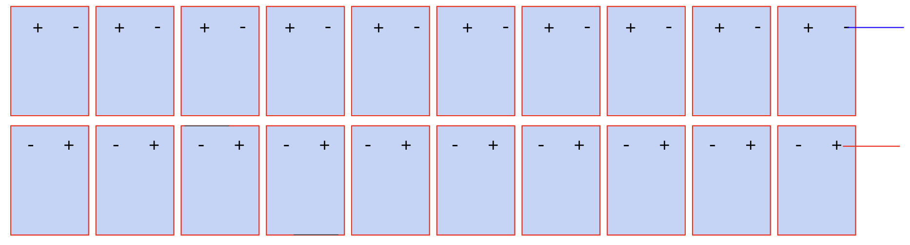
DC cable on a ground mount system
How much do you use?
A common question with larger roof and ground mount systems is how much cable is required and calculations need to be made in order to cost the job correctly. In this article we look at DC cable, how much, what kind etc.

System design
The assumptions:
- Using 400 watt panels
- 1690 mm long and 1046 mm wide
- Configured in Portrait
- 2 x tiers
In addition looking at:
- 20 x panels per string
- Gap between tiers is 25 mm
- Gap between panels is 25 mm
- No parallel strings
- Inverters all on back of last row
- All DC runs from middle of the row to middle of last row
Panel layout
Per row there are 8 x strings of 20 x 400 watt panels per string so row length is approximately 85 metres wide.
There are 20 rows, total distance, North South with spacing is 142 metres which includes the 4 metre North and 4 metre South perimeter roads.
Where is the system located?
Where a system is located and the pitch of the array both play a role in regards to panel row spacing and hence DC cable runs.
In this case we are assuming:
- Location is Laverton, Melbourne, Victoria
- Spacing between poles is nearly 7 metres ( between rows)
- Panels at 30 degree pitch
- Total number of panels is 3200,
- 1.28 MW system
So where do we start
First we determine the overall width of the row and in this case it is approximately 85 metres made up of 80 panels per tier and there are 2 x tiers.

In this case the combined length of the positive and negative cables per row is approximately 256 metres
Made up of:
- 4 x runs of 31 + metres
- 4 x runs of 21 + metres
- 4 x runs of 11 + metres
Each string’s horizontal distance has been calculated at 10.65 metres. The string is across two tiers, 10 panels per tier and takes into account the panel width and the gaps between the individual panels.

What we now know
First row uses 256 metres of cabling
- In this case all rows are the same length
- There are 20 rows in total
- So 20 x 256 metres is the amount of cable used within the rows
- Approximately 5120 metres
What next?
From the centre of each row there is a cable run that travels all the way to the inverter station that is situated behind the last row.
As there are no parallel strings and there are 8 x strings per row this means that there are 16 x DC cable runs per row back to the inverters.
Now the calculations?
In regards to the row furthest away from the inverters ( we will call this row 1) the distance is 133 metres* and this calculation was made using:
- CEC location data, panel angle, panel dimensions and was covered in a previous presentation
- This means that there is 16 in total cables @ 133 metres each so a total of
- Approximately 2130 metres.
*North South distance of 8 metres subtracted

DC cable on a ground mount system
What about the next row?
As we progress closer to the inverter station row by row the total distance reduces by the distance between the panels, centre to centre by a certain factor, in this case it is approximately 7 metres ( distance between the poles)
So in the case of the next row, row 2 the calculation is 16 x (133 -7) = 2016 metres.
Now the last row?
Effectively we subtract the distance between the panels using the pole positions for each row then multiply this distance by the number of cables.
As the inverters are positioned on the back of the last row this run is negligible. In this scenario I have assumed 1 metre to inverters so the last row run is 16 x 1 = 16 metres.

So how much cable?
- We have a 1.28 MW solar system
- Consisting of 3200 x 400 watt panels
- Total cable distance is approximately 27,500 metres

Things to think about
- Should we parallel the strings?
- What about voltage drop calculations?
- What percentage increase should I allow for bends?
- What about mistakes?
Conclusion
Large solar projects, both ground mount and roof mount require a considerable amount of DC cable so there is definitely a need for a process and procedure that allows accurate calculations of these runs. This is part one of a three part series.
If you’d like to see more of what Greenwood Solutions get up to in the real world of renewable energy, solar, battery storage and grid protection check out the following pages:
https://www.greenwoodsolutions.com.au/industry
https://www.greenwoodsolutions.com.au/commercial
https://www.greenwoodsolutions.com.au/commercial/customer-stories
https://www.greenwoodsolutions.com.au/news

Training videos
Every week we publish new videos and walkthroughs online.


